If you’re background is not one that has you familiar with commonly used terms in mechanical design, mechanical engineering, product development, CAD, or manufacturing, this page might be useful to you.
Basically, it’s intended to be a laypersons guide to the words and phrases that I’m used to using on a daily basis. This is mean to give you just enough information to be dangerous, or more importantly, have a basic background before you approach someone for help in this area. Feel free to add suggestions in the comments for other words and phrases and I’ll do my best to keep this up to date. The goal is to keep this “un-technical” with links to more detailed information. It is by no means all encompassing and I will be adding to it over time. Please use the comments to make suggestions for the list (corrections, new terms, recommended links, etc). Thanks!
The Mechanical Design Terminology Guide
A | B | C | D | E | F | G | H | I | J | K | L | M | N | O | P | Q | R | S | T | U | V | W | X | Y | Z
[dropcap]A[/dropcap] Back to Top
ABS: A plastic commonly used in injection molding and 3D printing. Most of those plastic parts you have around your house are made of ABS. (Matweb.com)
Assembly: When two or more parts have to be put together in some way.
[dropcap]B[/dropcap] Back to Top
Backlash: The “slop” felt in a mechanical system, typically when the system reverses direction. Parts require clearances to assemble correctly, and these clearances can be felt in moving assemblies. (Wikipedia)

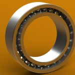
Ball Bearing
Bearing: A bearing helps things move. Typically, bearings make it easier for parts to slide or rotate, and to do so for a long time without wearing down. (Wikipedia)
Boss: A generic term that describes something that sticks up on a part. An plastic part may require a hole for a screw, so the designer will add a round boss to make room.
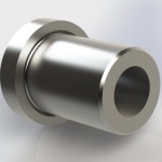
Bushing: Sometimes used as a bearing, a bushing is typically a hollow cylinder used as an interface between a hole and a shaft.

Bushing
[dropcap]C[/dropcap] Back to Top
CAD: “Computer Aided Design” or “Computer Aided Drafting”. Basically, this is a general term for using a computer to help you design things in 2D or 3D.
CAM: “Computer Aided Manufacturing.” CAM jumps in where CAD leaves off. Once it’s designed, CAM programs help engineers and operators tell computer controlled machines how to make things.
Casting: A “cast” part is one that is made by pouring liquid into a mold.
Chamfer: Sharp edges are often bad things to have on finished parts. They wear down easily and may even be dangerous. Chamfers are angled cuts added to the edges of parts.
Conceptual Design: Working at a high-level to nail down the big idea. Trying to avoid any unnecessary detailed design work.
Counterbore: A hole with a flat bottom, usually around a smaller hole. Counterbores are often used to hide the head of a screw.
Crowdfunding: Pooling the finances of large numbers of people to fund a project, product, or business. (Wikipedia)
Crowdsourcing: Using large groups of people to generate and refine ideas. (Wikipedia)
[dropcap]D[/dropcap] Back to Top
Datum: A datum is a reference feature that helps you interpret dimensions on an engineering drawing. (Wikipedia)
Detailed Design: Going from high-level conceptual design to something that can be manufactured. This typically includes drawings for all of the parts and assemblies required.
DFA: “Design for Assembly”. In other words, how easy will this thing to be to put together? An elegantly placed screw may not seem so great when you realize there’s no way for a screw driver to reach it. (Wikipedia)
DFM: “Design for Manufacture”. By understanding how things are going to be made, you can design them to better accommodate these manufacturing processes. It’s not uncommon for an inexperienced engineer to make parts unnecessarily expensive by creating features in their 3D model that are not ideal for the intended manufacturing process. (Wikipedia)
Drawing: When I say “drawing”, I’m referring to a technical document that describes the necessary information to produce a particular part or assembly. Drawings come from CAD packages and conform to commonly accepted standards.
[dropcap]E[/dropcap] Back to Top
Eccentric: When you offset the axis of two cylinders, you create an eccentric motion. Rotating one cylinder on axis creates moves the other cylinder in a rotary motion.
[dropcap]F[/dropcap] Back to Top
Fillet: A fillet simply refers to a radius added between two intersecting surface. They might be added for aesthetics, strength, or to make a part simpler to produce.
Fixture: A tool that helps you do something during the manufacturing process. Fixtures ensure you can perform the same process over and over again and get the same result.
[dropcap]G[/dropcap] Back to Top
Gear: A part with teeth used transfer motion. (Wikipedia)
[dropcap]H[/dropcap] Back to Top
[dropcap]I[/dropcap]Back to Top
Industrial Design(er): Industrial design tends to refer to the look, feel, and human interaction with a product. Often times an industrial designer will be responsible for developing the look (shape, color, textures) of a product. Mechanical engineers design the functional product around these constraints.
Iterative Design: Even when you think you know exactly what you want, the process of designing, prototyping, and testing will always produce changes. You should expect this to happen.
[dropcap]J[/dropcap]Back to Top
[dropcap]K[/dropcap]Back to Top
[dropcap]L[/dropcap] Back to Top
Lead In: A feature used to help locate parts together. A pin might use a chamfered edge to help guide itself into a hole.
[dropcap]M[/dropcap] Back to Top
Mechanism: When something in the design needs to move in some controlled manner. (Wikipedia)
Mold: A tool used to make copies of a part. You pour in a liquid and take a out a solid.
[dropcap]N[/dropcap] Back to Top
[dropcap]O[/dropcap] Back to Top
[dropcap]P[/dropcap]Back to Top
PDM: “Product Data Management.” Exactly what it sounds like, managing all of the data associated with a product like 3D models, drawings, manufacturing plans, etc. (Wikipedia)
Pitch: Typical of screws and gears, it describes the numbers of threads or teeth over a given distance. For threads or gears to properly mate, they must have the same pitch.
Preload: A 50lb weight sitting on the ground has a 50lb preload to the ground. It will require at least 50lb of force opposite the ground to break contact. In mechanical assemblies, things like bolts and springs are used to create preload to ensure things stay where they are supposed to.
Prototype: Simply a mock-up of the desired end result. This can be done digitally, with 3D models, renderings, and animations. It can also be done physically using tools like 3D printers.
[dropcap]Q[/dropcap] Back to Top
[dropcap]R[/dropcap] Back to Top
Rendered Image: Using 3D CAD data to generate realistic images of a design, product, or idea. Rendered images simulate the behavior of light and typically take hours to generate at high resolutions. Many product images you see in advertising and on web sites are actually rendered from 3D data, even though they may look like a photograph.
Rendered Animation: CAD data can be used to demonstrate a products function, how it goes together, or just move it around in space. When we render each frame of the animation, we can bring ideas to life on the screen.
[dropcap]S[/dropcap] Back to Top
[dropcap]T[/dropcap]Back to Top
Tapped Hole: A hole that has threads for a fastener to engage.
Tolerance: The allowable range on a dimension. If you want something 1.00″ thick, you have to specify how close to 1.00″ is acceptable, so you add a range like +/- .02. (Wikipedia)
Tooling: This generally refers to the production equipment required to mass produce a product. Large up front costs are amortized over large production runs.
[dropcap]U[/dropcap] Back to Top
[dropcap]V[/dropcap] Back to Top
[dropcap]W[/dropcap] Back to Top
[dropcap]X[/dropcap] Back to Top
[dropcap]Y [/dropcap] Back to Top
[dropcap]Z[/dropcap] Back to Top
Zalaco: An awesome company that people love 🙂
