Mechanical Design Engineering
 When someone asks what I do, I usually say that I am a “mechanical design engineer.” A “mechanical designer” applies knowledge of physics, materials, and engineering to design components, mechanisms, and systems that work in the real world. In industry, mechanical design engineers are responsible for the physical characteristics of everything that gets produced. We maintain the design in a 3D CAD system. We produce engineering drawings (and maintain proper revision control). We work with suppliers to get parts made. And like all engineers, we love solving problems.
Design for Manufacture (DFM)
Design for manufacture is about understanding the manufacturing impacts of design decisions throughout the design process. Good mechanical design engineers understand how parts are manufactured. We also recognize what manufacturing method is best for a particular application. Should a part be designed for injection molding? Should it be machined from aluminum? Or cast in steel? Once we answer that question, the design of the part itself needs to be reflective of that decision.
Design for Assembly (DFA)
Have you ever put something together where you could barely reach one of the screws? Imagine an assembly line of works perpetually not being able to reach the same screw. Good designs account for assembly early in the process. When done correctly, you’ll never even know it was taken into consideration – it just works.
Kinematic Design
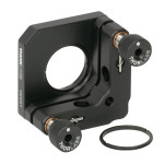
ThorLabs Kinematic Optical Mount – Three Spheres Contacting a Plane
“Kinematics” is just fancy way to describe how a three-legged chair will never wobble, but a four-legged one always will. That’s because three points make a plane. It doesn’t matter how uneven the three legs are, they will all touch the ground (even if you’re sitting at an odd angle). This is why your dining table chairs often have those little adjusters on the bottom (otherwise, they’d have to be perfect!).
Understanding kinematics just means that we don’t want to over-constrain our mechanical systems. Good mechanical design is built on a sound understanding of kinematic principles.
Machined Part Design
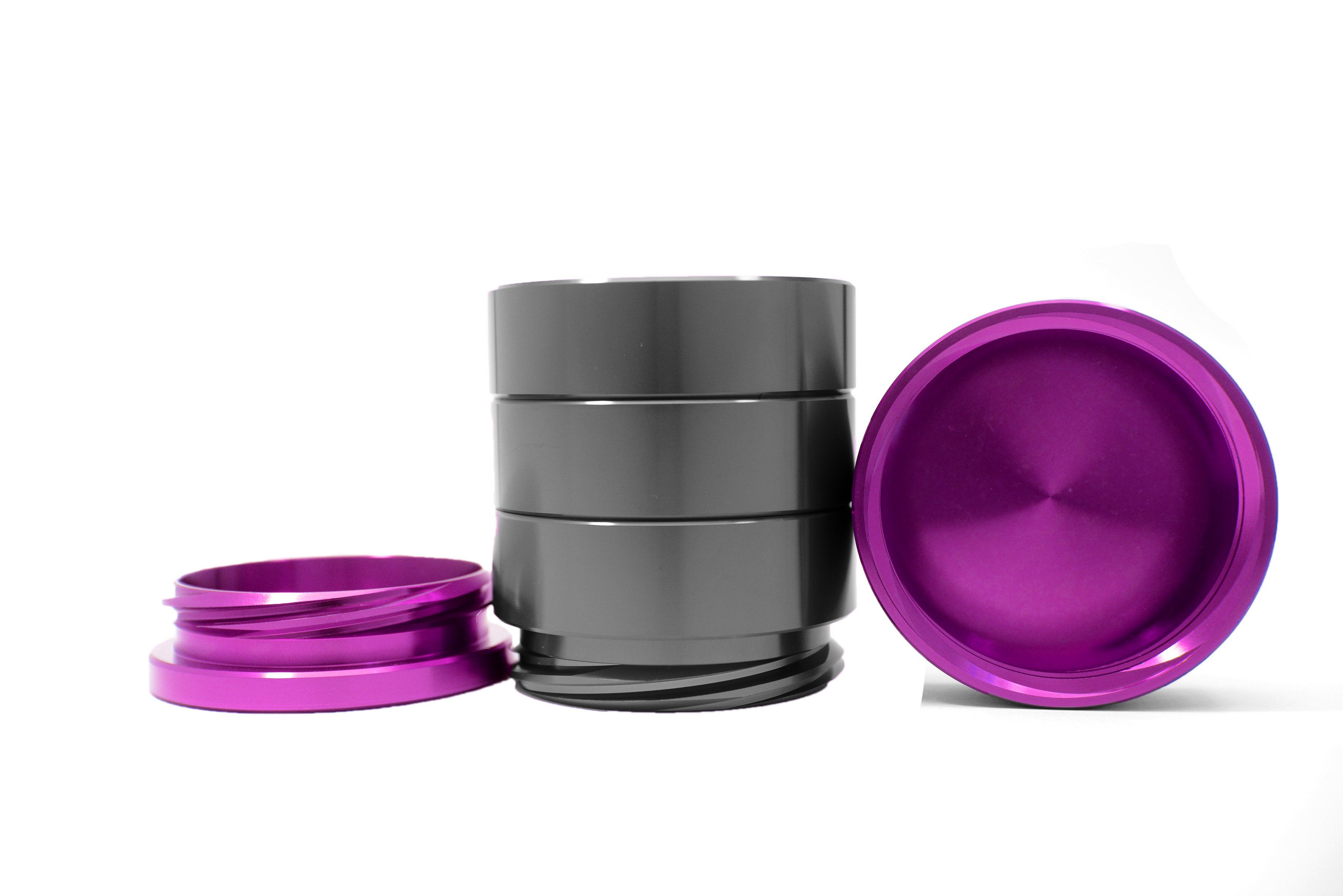
Machined Aluminum Parts – Anodized Gunmetal and Pink
Machining is a subtractive manufacturing process. You start with a chunk of material, in some shape, and use various tools and machines to remove material until it reflects the desired form. Milling, turning, and drilling are examples of machining. While modern machining can create almost anything you can imagine, there are both costs and limitations.
I have extensive experience designing machined components. I’ve designed complex machined housings for high-powered laser systems, frames to hold engines inside of cruise missiles, and precision mounts to hold optical components. If you require assistance with designing or documenting machined parts, you’ve come to the right place.
Molded Part Design
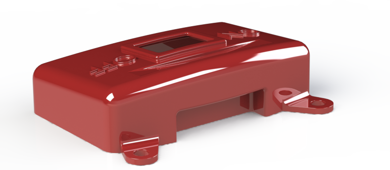
Molded Cover Design
Injection Molded components are used everywhere. Most consumer products are made up of molded parts because of the low cost at high volume. Up front tooling can be expensive, but produces parts that can sometimes cost just a few cents a piece.
The material options for injection molding are almost limitless. Any product that will produced at mass-production scale will likely benefit from the use of injection molding. Proper design will lead to parts that cost less (because the tooling will be less complex), and parts that look and perform as intended. Poorly designed parts can have all kinds of defects due to the nature of cooling down very hot plastic very fast. Make sure your parts are designed right before investing in your tooling.
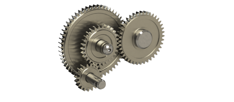
Mechanism Design

DeltaMaker Rendered Image
When a system of parts is used to create motion, we call that a mechanism. The DeltaMaker 3D printer is a great example. Three carriages are moved only vertically, connecting to a central end effector. This is an example of a parallel robot. No matter what position the carriages are moved to, the end effector maintains it’s position parallel to ground.
Three degrees-of-freedom (DOF) are constrainted – the end effector cannot pitch, roll, or yaw. All of its rotational degrees-of-freedom have been constrained. But it’s translational degrees of freedom, motion in X Y and Z, have not been constrained.
The carriages are driven vertically by a belt-and-drive system – each carriage having its own stepper motor to control vertical position.
Engineering Analysis
How much pre-load is that bolt pattern generating? How stiff of a spring do we need to hold our mechanism together? What is the maximum load that a component can support? Those are the kinds of questions we answer with mechanical analysis. Sometimes this involves simple hand calculations. Sometimes an Excel or MathCAD worksheet is what we need. Other times, advanced computer simulation is necessary. While Zalaco is not a full-service engineering analysis firm, we may be able to provide guidance or some first-order analysis to assist you.
Let’s Get Started Together
Schedule a Free Phone Consultation
Use the form below to schedule a phone call with me. It’s quick and easy way to make sure we’re both available for a discussion. You’ll get a confirmation email as well as a reminder, then I will call you at the scheduled time.
Or Send Me an Email
Comments or questions are welcome.